Intrinsically Safe Instruments Help to Minimize Risks in Hazardous Locations
 Intrinsic Safety Applications
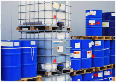
- Hazardous material storage facilities
- Automotive paint booths
- Inlet monitoring of gas turbines
- Organic coating manufacturing
- Spray finishing areas
- Petroleum dispensing areas
- Solvent extraction plants
- Utility gas plants and facilities
- Aircraft hangars
- Fuel servicing areas
- Petroleum refining facilities
Intrinsic safety (IS) is a concept that is used to prevent electrical equipment from causing explosions in hazardous environments. A hazardous environment is a location where potentially explosive mixtures of gases or fine powders are expected to exist. Electrical equipment has the potential of igniting these mixtures if sparks or high temperatures are generated during the operation of the equipment. In an intrinsically safe system, all of the equipment is designed and installed in such a way that it does not have enough energy to cause ignition of the potentially explosive gas mixture, even in a fault condition.
Another approach to preventing explosions is to install electrical equipment inside of “explosion proof” housings. These housings can withstand ignition of any explosive gases that may be present within the housing, eliminating the propagation of flames into the hazardous environment. Explosion proof systems can be large, heavy, and expensive. Intrinsically safe systems offer a variety of advantages over explosion proof systems. However, intrinsic safety is only feasible for low voltage devices that require limited power (instrumentation, thermocouples, etc.). High voltage, high power devices cannot be intrinsically safe by their very nature.
The Elements of an Intrinsically Safe System
An intrinsically safe (IS) system includes the IS device that is located in the hazardous environment, a power limiting device (IS barrier or galvanic isolator) located in a nonhazardous area, and the associated wiring.
IS devices typically operate on low voltage DC and consume less than 1 watt of power. For a manufacturer to achieve IS certification of a device, the design and the apparatus itself must be inspected and approved by an appropriate regulating authority (for example, FM, CSA, PTB). When IS devices are correctly installed and connected, they are incapable of creating sparks or heat that could cause ignition of the hazardous environment.
IS devices must always be connected to power limiting devices, such as intrinsically safe barriers or galvanic isolators. These barriers are located in a safe, non-explosive environment. They are placed between the electrical power supply and the IS device. Their purpose is to limit the voltage and current available to the IS device that is in the hazardous environment. Wire runs can change the electrical characteristics of a circuit and must therefore be considered as part of the overall system. Wiring of IS systems must be done according to standards created by regulating authorities.
Configuring Intrinsically Safe Elements Together
 The elements of IS systems can be organized in several different ways.
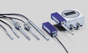
For example, IS barriers may be incorporated within an instrument, such as a humidity transmitter with a remote sensor. The electronic portion of this instrument would be installed in a safe environment and the remote probe installed in the hazardous environment. Such a system would include all of the necessary elements for an IS installation and would free the user from having to specify and acquire IS barriers. However, the electronic portion of the instrument could never be mounted in a hazardous location, seriously limiting the flexibility of installation.
Another approach is to separate the IS barriers from the instrument. This is how Vaisala’s IS humidity instruments are designed. In this case, the entire instrument and probe can be mounted anywhere within the hazardous environment. Power and signal wires terminate at the IS barriers in the safe environment. This allows for flexibility in installation, but it also requires that the user specifies and acquires barriers that are appropriate for the installation.
Installation Guidelines
- Installation guidelines are specific to each regulating body by which the IS device is approved.
- Guidelines can be used to specify and select an appropriate IS barrier or galvanic isolator.
- Factors to consider are the power supply and the electrical characteristics of the device where the signal wires will terminate.
- Maximum load calculation should be made to ensure the total circuit impedance does not drop the voltage below minimum threshold voltage for correct operation of the IS device.
- Users should contact the manufacturers of IS barriers or galvanic isolators for help in selecting these devices.
Source: Vaisala