Deadweight Pressure Testers
Deadweight Pressure Testers obtain pressure by the combination of a mass, typically weights, which are floated on a cylinder and piston combination with a defined area. The deadweight tester’s basic equation is:
P = F/A
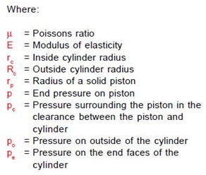
Where:
P = the pressure being derived
F = the force applied by the weights
A = the effective area of the piston cylinder
2.1 Piston Gage Type Deadweight Testers
Inside a deadweight tester or piston gage, a platform that contains weights that are calibrated is balanced on a piston that’s floated in a cylinder. The used fluid could be either a hydraulic deadweight tester, a liquid,a gas, or a pneumatic deadweight tester.
Piston gages commonly incorporate three designs of cylinders; the simple cylinder, the reentrant cylinder, and the controlled clearance cylinder.
2.1.1 Simple Piston and Cylinder
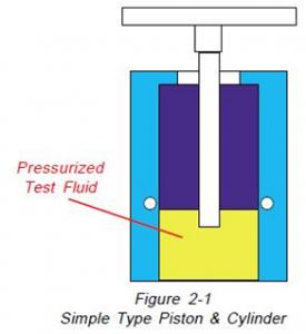 As shown in Figure 2-1, within the simple piston and cylinder design, the test fluid is connected to a chamber below the interior of the cylinder, the weights are hanging on the piston and the piston is floated upon the pressurized test fluid.
Since the pressure is applied only to the cylinder’s interior, it increases pressure resulting in the reduction of the piston diameter and expansion of the cylinder bore, thus the effective area of the combination gets increased. This mixture of effects results in an increased clearance between the piston and cylinder. This increased clearance results in increased leakage of the test fluid, thus limiting the available test time before fluid replenishment. For these reasons, the simple piston cylinder design is used primarily within cylinder gages and pneumatic piston and hydraulic piston and also cylinder gages below 10000 PSI (690 bar).
2.1.2 Re-entrant Piston & Cylinder
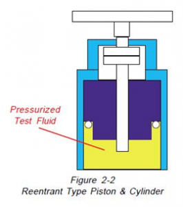
As shown in Figure 2-2, in the cylinder design and re-entrant piston, the test fluid’s connected to a chamber on the cylinder’s outer part as well as being connected to the interior of the cylinder. In operation, since the area of the outside of the cylinder is larger than the inside increasing test pressures will decrease the bore of the cylinder, especially reducing the piston’s diameter. The net effect of these reductions will be to reduce the effective area and clearance between the piston and cylinder at high pressures. The available test time is not restricted by the excessive loss of test fluid. The cylinder design and re-entrant type piston are used in all pressure ranges, including high pressures exceeding 50000 PSI (3450 bar).
2.1.3 Controlled Clearance Cylinder and Piston
The controlled clearance cylinder and piston are almost identical to the re-entrant cylinder and piston except that the chamber on the outside of the piston and cylinder is connected to a separate source of calibration pressure. As shown on Figure 2-3,
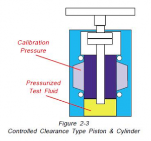 at each point of pressure measurement, the calibration pressure is adjustable to maintain the effective diameter of the cylinder. In operation, this type of piston gage although very accurate is very slow to operate and very expensive to purchase. It is used primarily by standards laboratories like the United State’s National Institute of Standards and Technology (NIST).
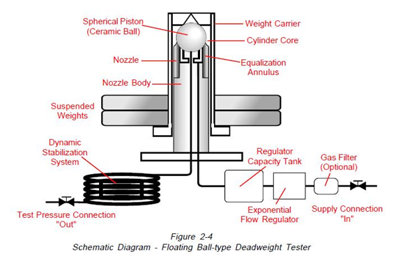
2.2 Ball Type Deadweight Tester
Pressure is measured with Ball type deadweight gages in respect of force over the area of unit. These instruments function the same as piston gages excluding the fact that a ball is utilized rather than a piston.
A schematic diagram of the AMETEK ball gage is shown in Figure 2-4. In this instrument, clean air is supplied from a flow regulator to an equalizing annulus and from there to a spherical chamber under the ball and to the output port. In operation, the ball, with a weight hanger and weights suspended from it, floats on a film of air with virtually no friction. In the area where the circumference of the ball is situated, the nozzle bore is tapered.
This taper permits a variable exhaust flow which functions in a pneumatic feedback loop together with the flow regulator to maintain the ball in a vertical position that’s fixed. Pressure builds up in the spherical chamber below the ball until the ball and the weights are suspended. The pressure within the spherical chamber is ported through stabilizing tubing to eliminate pressure oscillations.
2.3 Other Types of Piston Gages
A vacuum-backed piston gage is made to measure absolute pressure. This instrument is almost the same as the conventional piston gage, but both the cylinder and piston and the weights operate in a vacuum evacuated bell jar. The pressure within the evacuated chamber must be measured accurately to arrive at the total absolute pressure being measured by the instrument.
The tilted piston gage is designed to operate at lower pressures. Since lower pressures are limited by the piston’s weight itself, the weight can be decreased by utilizing a hollow piston, which comes with a vacuum, and tilting the assembly.
2.4 Intrinsic Correction Terms
As described by P.L.M. Heideman and B.E.
Welch, United States National Institute of Standards and Technology1, the pressure P generated by a piston gage at its reference level is given by the following equation: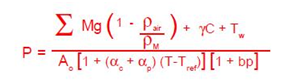
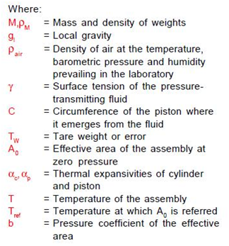
2.4.1 Air Buoyancy Correction
The term (1 – Pair/Pm) is the air buoyancy correction for weight M. The density of brass weights is 8.4 grams/cm3 and the density of stainless steel weights is 8.0 grams/cm3. The density of moist air has been tabulated 2,3. It can be computed from the equation: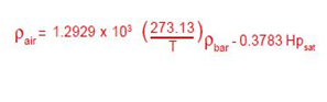
2.4.1.1 Air Buoyancy
The air buoyancy correction must be carefully evaluated. For measurement at 23°C, 30% relative humidity, stainless steel weights and 1000 mb barometric pressure, the correction would be 0.00147% or 147.5 ppm.
2.4.2 Thermal Expansion
The term [1 + (‹c+ ‹p)(T – Tref)] corrects the area for thermal expansion. This correction does not contribute significantly to accuracy. For a tungsten carbide piston inside a steel cylinder the correction amounts to 17 ppm or 0.000017% with T-Tref = 1°C.
2.4.3 Surface Tension
The term ƔC describes the force generated by the surface tension of the fluid acting on the piston where it emerges from the fluid. is the surface tension of the fluid and C is the circumference of the piston. The value of Spinesso 38 is representative of many oils used in piston gages. For a piston of 32 mm2 cross-sectional area this correction amounts to about 10-4 Newtons. At high pressures, this constitutes a minimal correction, but for low pressure oil gages, it should always be taken into account. This correction does not apply to air-operated gages.
2.4.4 Tare Force
TW is the tare force that may result from an error in the determination of the mass of one of the weights or in the computation of the head corrections; it might also be characteristic of a gage.
2.4.5 Area
A0 is the cross-sectional area of the piston. This area can be determined in two different methods. The first method is to perform numerous measurements of the diameter along the piston’s length and transform these measurements by utilizing a suitable mathematical model. An alternative method is to cross-float a piston against another piston or instrument of known pressure or effective area.
2.4.6 Pressure Coefficient
The term (1 + bP) describes the change of effective area with pressure. This is the most important correction term. The pressure coefficient is determined by the mathematical expression1:
Depending upon the design and the materials of the construction of a piston and cylinder, the pressure coefficient can be either negative (Area decreases) or positive (Area increases), and\ under certain conditions it could approach zero (Constant area).
2.5 Site Location Correction Factors
AMETEK Certification of Accuracy states each deadweight tester’s accuracy is based on specific conditions for gravity and temperature. Corrections to the pressures stated in the Certification can be made to compensate for the actual conditions at the test site as follows:
2.5.1 Gravity
If the local gravity at the test site is different from the gravity for which the deadweight tester was calibrated, the actual pressure as shown on the
The Calibration Report can be converted to actual pressure at the test site through the use of the following formula:
PL = PA x GL/G
Where:
PL = Actual Pressure at the local gravity of the test site
PA = Actual Pressure as shown in the Calibration Report
GL = Local Gravity in Gals. (cm/sec2)
G = Gravity for which the deadweight tester was calibrated in Gals. (cm/sec2)
A reading of 3000 PSIG is an instance of this correction, taken at a site with a local gravity of 979.2 Gals., the tester calibrated for International standard gravity 980.665 Gals.
PL = 3000 x 979.2/980.665
or
PL = 2995.518 PSIG
2.5.2 Temperature
If the temperature at the test site is different from the temperature for which the deadweight tester was calibrated, the actual pressure as shown on the Calibration Report can be converted to actual pressure at the test site through the use of the following formula:
PL = PA + PA x A ( TS – T )
Where:
PL = Actual Pressure at the temperature of the test site
PA = Actual Pressure as shown on the Calibration Report
A = Thermal Coefficient per °C as shown on the Calibration Report
TS = Temperature in °C at the test site
T = 23°C, the Reference calibration Temperature
An example of this correction would be a reading of 100 Inches of Water (60°F), taken at a site with a local temperature of 40°C (104°F). The AMETEK Model PK II Deadweight Tester consists of a 0.0000167 per °C thermal coefficient.
PL = 100 + 100 x 0.0000167 (40 – 23)
= 100 + 0.02839
= 100.02839 inches W.C.
2.5.3 Test Level
If the instrument being calibrated by a deadweight tester is not at the same height as the tester, compensation for the difference in height must be made. This compensation can be made using the following formula:
PL = PA + PA x ( HI – HT) x Df
Where:
PL = Actual pressure applied to the instrument under test
PA = Actual pressure shown in the Calibration Report
HI = The calibration height of the deadweight tester (A height line is on the T & R weight carrier, the major diameter of the PK II ball).
HT = The calibration height of the instrument being calibrated.
Df = Density of the fluid being used for calibration (Oil,water, etc.)
An example of this correction would be a measurement of 100 PSIG, using an AMETEK Model T tester (H2O), where the instrument being calibrated is located on a platform 20 feet (6 meters) above the tester:
PL = 100 +( 0 – 20) x 62.4 #/ft.3/144
= 100 – 8.666
= 91.334 PSIG
2.6 Traceability and Uncertainty
The parameters of both traceability and uncertainty are concerned with the accuracy of measurement within the laboratory that conducted the testing on the pressure standard. Traceability is a measure of the ability of the laboratory to trace the calibration of a pressure standard through a direct chain of calibrations to a national standards laboratory such as the United States National Institute of Standards and Technology. Uncertainty is an estimate of the measurement accuracy of the traceability chain of calibrations.
2.6.1 Traceability
Traceability in the United States is defined as the ability to demonstrate conclusively that a particular instrument or artifact either has been calibrated by NIST at accepted intervals or has been calibrated against another standard in a chain or echelon of calibrations eventually resulting in a calibration performed by NIST4.
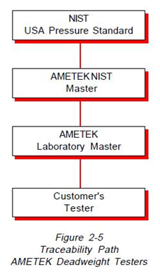
All testers produced by AMETEK are directly traceable to NIST. This traceability of deadweight testers is shown in Figure 2-5. As shown on this diagram, master testers are sent by AMETEK to NIST on a regular interval for testing. These master testers are then utilized on an annual basis to calibrate working master testers in the AMETEK Standards Laboratory. The working masters are used to test and calibrate all new and repaired testers before shipment.
2.6.2 Laboratory Uncertainty
In general, the result of a measurement, such as pressure, is only an approximation or estimate of the specific quantity subject to measurement, and the result is complete only when accompanied by a quantitative statement of its uncertainty. To state this in a different way, a measurement, such as accuracy, is only as good as the technique and equipment used to take the measure, and the accuracy of the standard against which the accuracy was measured. The overall uncertainty must take into account all testing between the national standard (NIST) and the instrument to which the uncertainty is assigned.
The measurement uncertainty of the deadweight testers has been estimated for all of the deadweight testers that are currently being produced. Within this analysis all of the terms which effect the calibration process were evaluated to establish an estimate of the uncertainty of pressure measurement within the AMETEK Standards Laboratory.
This measurement, when combined with the NIST uncertainty, is an overall uncertainty estimation of testers produced by AMETEK.
The factors contributing to uncertainty of the AMETEK Laboratory included the following:
1. Laboratory conditions. The effect of temperature, pressure and relative humidity on the air density in the vicinity of the weights.
2. Accuracy of the mass values that were used
to certify the balances used to measure weights at AMETEK.
3. The effects of surface tension, fluid head and thermal expansion on the piston during the testing.
4. The sensitivity and uncertainty of the cross-float measurement instrumentation.
5. The uncertainty of the master testers is reported to AMETEK by NIST.
6. The local gravity at the AMETEK laboratory.
7. The pressure range of calibration on each dead weight tester.
Currently, equipment specifications and advertisements include only claims on the accuracy of deadweight testers and do not include uncertainty of the accuracy measurement. The traceability path and uncertainty measurement within the AMETEK Pressure Standards Laboratory as reported are well above the industry average.
Future efforts on a United States national level including laboratory accreditation (Already in place in Europe and Asia) should require that both the accuracy and uncertainty levels of instruments such as deadweight testers be reported.
Source by: AMETEK